Time-of-Flight Measurement: Principles, Errors, And Limits
By Greta Lund • 21st May
Time-of-flight measurement sits at the intersection of distance measurement principles, photonics, and timing electronics. For manufacturing, automation, and metrology teams, it is increasingly the backbone of lidar scanners, safety curtains, robot guidance, and inline dimensional checks. When it is engineered and documented correctly, it can deliver repeatable, traceable distance data under real shop conditions. For a practical primer on why traceability matters beyond marketing specs, see measurement traceability basics.
If it isn't documented, it's hope, not evidence under pressure.
This guide focuses on how time-of-flight (ToF) systems work, what drives their limits, and how to treat them as engineered measurement systems rather than black boxes.
1. Fundamentals Of Time-Of-Flight Measurement
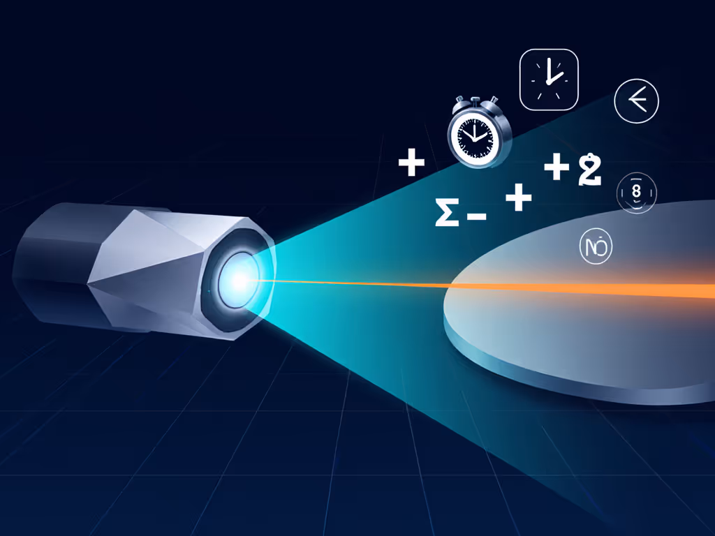
1.1 Basic principle
At its core, a ToF system:
- Emits a signal (typically light, sometimes sound or radio).
- Waits for the reflection from a target.
- Measures the elapsed time (t) between emission and detection.
- Converts time to distance using
\[ d = \frac{v \cdot t}{2} \]
where:
- (d) = one-way distance sensor-target,
- (v) = propagation speed of the signal in the medium (≈ speed of light in air for optical ToF),
- division by 2 accounts for the round trip.
This is the same physics behind laser rangefinders, industrial lidars, and time-of-flight cameras.
1.2 Carriers and domains
While ToF is often associated with optical lidar, the same principle appears in several domains:
- Optical / laser ranging fundamentals: near-IR lasers or LEDs for lidar, scanners, and 3D cameras.
- Ultrasonic: slower propagation speed, easier timing, shorter range and lower precision.
- Radio / UWB: used for indoor positioning and tracking where line-of-sight may be intermittent.
For precision manufacturing, optical ToF is usually the relevant case, so the rest of this article assumes light as the carrier.
2. Pulse vs Phase Lidar: Two Main ToF Approaches
Time-of-flight can be implemented with direct pulse timing or indirect phase measurement. This pulse vs phase lidar distinction is essential when you interpret specifications or build an uncertainty budget.
2.1 Direct (pulse) ToF
The system emits short laser pulses and measures their absolute return time.
- Measurement quantity: absolute time delay.
- Timing electronics: fast time-to-digital converters or high-speed counters.
- Strengths:
- Very long range possible with suitable optics and pulse energy.
- Good for discrete distance measurement or scanning.
- Limitations:
- Sub-millimeter accuracy demands picosecond-level timing, which pushes cost and complexity.
- Pulse shape and detector thresholds introduce nonlinearity ("walk error").
2.2 Indirect (phase) ToF
Here a continuous or high-duty-cycle modulated light source is used. The system measures the phase shift between emitted and received modulation.
- Measurement quantity: phase shift (\phi) of a modulation signal.
- Distance relation:
\[ d = \frac{v}{4\pi f_m} \phi \
where (f_m) is the modulation frequency.
- Strengths:
- High repeatability at modest cost.
- Well suited to 2D/3D ToF cameras with per-pixel ranging.
- Limitations:
- Range ambiguity: distance repeats every modulation wavelength; requires multiple frequencies or other strategies.
- Sensitive to multipath reflections causing phase bias.
2.3 Implications for shop-floor use
- For single-spot distance or thickness checks over tens of meters, pulse ToF lidar is common.
- For 3D mapping of parts, pallets, or workcells, phase-based ToF cameras dominate.
- For both, your measurement plan must reflect whether the instrument reports absolute range, ambiguous range, or processed 3D point clouds.
3. Anatomy Of A ToF System
A typical optical ToF system includes:
- Light source - laser diode or LED, often near-IR; pulse or modulated.
- Optics - emit and receive lenses; sometimes scanning mirrors.
- Detector - photodiode, avalanche photodiode (APD), or single-photon detector; in cameras, an array.
- Timing / demodulation electronics - counters, phase detectors, ADCs.
- Signal processing - filtering, averaging, background subtraction, outlier rejection.
- Calibration model - maps raw counts/phase to distance, usually including offsets, scale factors, and temperature compensation.
From a quality-systems perspective, the last two blocks are where most undocumented changes turn into audit findings. Firmware updates, new filtering modes, or modified calibration coefficients must carry revision callouts and evidence of verification.
4. Distance Measurement Error Sources
ToF instruments often advertise impressive nominal resolutions. The meaningful question for you is: what is the total uncertainty under my conditions? That requires understanding distance measurement error sources end to end.
4.1 Instrumental errors
- Timing jitter: noise in emission and detection timing → random distance noise.
- Clock inaccuracy or drift: systematic scale error in distance.
- Nonlinearity and walk: pulse shape dependence on reflectivity or distance → distance bias.
- Detector saturation: high return power flattens pulses or distorts phase.
- Internal alignment: misalignment between emitter and receiver axes.
Mitigation actions:
- Use factory-calibrated instruments with documented linearity tests.
- Stabilize supply voltage and temperature where feasible.
- Verify distance readings at multiple certified distances, not just one.
4.2 Target-related errors
- Reflectivity: dark or absorbing surfaces reduce signal-to-noise ratio.
- Angle of incidence: oblique surfaces reduce effective return; the beam may leave the field-of-view.
- Surface structure: rough or specular surfaces create multipath and mixed pixels in cameras.
Mitigation actions:
- Specify target condition in your measurement procedure (material, finish, angle tolerance).
- For ToF cameras, use masking or region-of-interest logic to avoid edges and holes.
4.3 Environmental effects on ToF
This is where shop-floor reality diverges from marketing brochures. For choosing the right technology by environment, see our guide on indoor ultrasonic vs outdoor laser accuracy.
Key environmental factors:
- Air properties: temperature, pressure, and humidity slightly change the refractive index → effective speed of light in air. For long paths, this becomes non-negligible.
- Aerosols: dust, mist, smoke, and coolant spray scatter and attenuate the beam, causing extra path length or loss of signal.
- Ambient light: sunlight or bright lamps add background to the detector, reducing dynamic range and increasing noise.
- Vibration and movement: both instrument and target motion during integration time smear distance readings.
Mitigation actions:
- Define environmental limits of use (e.g., temperature range, maximum airborne coolant density) in the control plan.
- Use shielding, shrouds, or optical bandpass filters to reduce ambient light and aerosols.
- Mount instruments on rigid, vibration-damped structures; synchronize measurements with machine motion when possible.
4.4 Data processing and human factors
- Filtering and averaging: improve repeatability but can hide dynamic errors or latency.
- Outlier rejection: thresholds may be inappropriate for new surfaces or fixtures.
- Operator assumptions: treating "distance to first surface" as "distance to datum face" without understanding beam shape and footprint.
Again, risk before convenience: resist the urge to "smooth it until it looks good" without documenting the processing chain and its implications for measurement uncertainty.
5. Practical Limits: Resolution, Accuracy, Range
5.1 Resolution vs accuracy vs repeatability
ToF datasheets often highlight resolution (smallest change in output) that is much better than true accuracy. If these terms ever blur together, review accuracy vs precision with practical examples.
- Resolution: set by timing counter granularity or phase quantization.
- Accuracy: depends on calibration, clock accuracy, modeling of environmental effects, and error sources above.
- Repeatability: short-term scatter, often improved by averaging.
For quality-critical work, treat the published accuracy as a starting point, then:
- Conduct your own gauge R&R under representative conditions.
- Build an uncertainty budget that includes environment, fixturing, and data processing.
5.2 Range and ambiguity
- Pulse ToF: maximum range limited by optical power, receiver sensitivity, eye-safety constraints, and timing window. Minimum range limited by dead time and near-field optics.
- Phase ToF: range limited by modulation frequency and ambiguity period; multiple frequencies are used for longer ranges.
Documented acceptance criteria should specify both range and minimum measurable distance for each application, not just "sensor must read the part."
5.3 Dynamic behavior
For moving targets or scanning systems:
- Integration time and averaging affect effective bandwidth.
- Mirror scan speed and sampling rate set point spacing in space.
- Latency between physical state and reported distance can be critical for safety functions.
Capture these behaviors explicitly in your measurement system analysis, especially where ToF feeds closed-loop motion or safety interlocks.
6. Implementation Checklist For Manufacturing Teams
To turn ToF capability into reliable decisions, treat it like any other critical measurement system.
6.1 Selection and design
Before specifying or purchasing a ToF sensor or camera, walk through:
- Measurement objective
- What dimension or feature are you controlling (gap, presence, profile, volume)?
- What is the tightest tolerance and target test accuracy ratio you need?
- Target characteristics
- Material, reflectivity, surface finish.
- Typical orientation and possible misalignment.
- Environment
- Temperature range and stability.
- Presence of dust, coolant, mist, or strong ambient light.
- Vibration levels and machine duty cycle.
- Geometry and range
- Required stand-off distance and clearance.
- Field-of-view or scan area; occlusions.
- Data and integration
- Required update rate and latency.
- Interface to PLC, robot controller, or SPC/QMS.
- Required traceability of raw data and processed results.
6.2 Control plan and documentation
Once the system type is chosen (pulse vs phase lidar, spot vs camera), lock down the documentation that will survive audits:
- Work instructions with:
- Defined setup distances and alignment steps.
- Target conditions and allowed variants.
- Environmental limits of use.
- Calibration procedure:
- Reference artifacts or distances and their traceability.
- Interval and acceptance criteria for drift.
- Actions on failure (lockout, adjustment, re-qualification).
- Version-controlled configuration:
- Firmware versions and parameter sets tied to asset IDs.
- Change control for filters, thresholds, and transformation algorithms.
- Evidence links:
- Storage of raw timing/phase data where practical.
- Clear linkage between calibration records, MSA studies, and production data.
A seemingly minor omission (such as an outdated revision of a ToF setup instruction at a critical station) can halt shipments even when the underlying physics is fine. The systems that sail through audits are those where behavior, configuration, and records move together under controlled change.
7. Where To Go Next
For teams considering or already using time-of-flight measurement:
- Start with a pilot cell: characterize errors and environmental sensitivity before broad rollout.
- Build a small uncertainty budget template specific to ToF instruments and require it for new applications.
- Coordinate with safety and controls engineers, especially when ToF is part of guarding or collision avoidance.
From there, explore:
- Comparative studies of pulse vs phase lidar for your specific surfaces and ranges.
- Improved environmental controls or shielding to tighten uncertainty.
- Integration patterns that feed ToF data directly into SPC and QMS with full traceability. For tool and workflow options, start with our roundup of wireless tools for SPC integration.
The goal is not just sophisticated sensing but defensible measurement: systems that deliver the right decision today and still stand up to scrutiny years later, when someone asks how you knew that distance was in tolerance.
Related Articles