Carbon Fiber Metrology: Choose the Right NDT Tool
By Priya Deshmukh • 20th Apr
Selecting the right carbon fiber metrology tools and composite material measurement equipment for your shop requires matching your tolerance stack to the tool's real-world capability (not its marketing claim). Every method trades speed, resolution, and cost. Pick wrong, and you'll either blow your audit with uncertainty estimates that don't hold up, or you'll waste cycles on overkill inspection. This guide walks you through the five most common non-destructive testing (NDT) approaches for aerospace composite inspection and teaches you how to build repeatability into your workflow.
Why Carbon Fiber Measurement Is Different
Carbon fiber composites pose a unique measurement puzzle. Unlike homogeneous metals, carbon fiber is a system: resin matrix, fiber orientation, ply stacking, and micro-voids all affect part integrity. A surface dimension might read perfectly, but if plies are delaminated or fibers are misaligned, the part is scrap. Traditional CMMs catch geometry; they don't catch the defects that kill performance in flight. For a broader comparison of options and when to use each, see our non-contact metrology guide.
Worse, carbon fiber's own properties make it a tricky material for measurement. The material is rapidly becoming one of the choice materials in the field of metrology due to its high stability and low thermal expansion, which is great for holding dimensions, but that same stability means your measurement setup must be even more disciplined, or thermal drift in your lab or shop floor will dwarf any real part variation. A standard carbon fiber part can be manufactured with a coefficient of thermal expansion (CTE) as low as 1.5 × 10⁻⁶ /K, nearly identical to Invar steel. This precision asset becomes a liability if your measurement environment isn't controlled.
If operators can't repeat it, it doesn't measure.
In my years coaching manufacturers through GR&R failures on composite parts, I've learned that the tool alone doesn't guarantee repeatability. The habit does. A team that's never been trained on when to use X-Ray CT versus fiber orientation scanning will burn cycles and still miss defects. And a technician who doesn't know the difference between a 10:1 test accuracy ratio and a 4:1 ratio will confidently sign off on parts that shouldn't ship. To set defensible ratios and limits, use our measurement uncertainty budget guide.
Five Core NDT Methods for Carbon Fiber
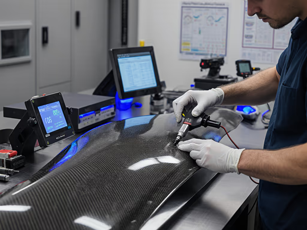
1. Fiber Orientation Measurement (Directional Scanning)
What it does: Uses directional illumination and high-resolution imaging to map fiber lay-up on the part surface. It reads the angle and pattern of fibers without damaging the part.
Practical specs: Modern systems (like the F-SCAN standard) achieve 40-60 µm resolution and scan at roughly 1 m/s, with a field of view around 50 × 50 mm. This means a wing skin section or fuselage panel can be scanned in minutes, not hours.
Best for:
- In-process verification of ply alignment measurement during lay-up
- Quick go/no-go checks on fiber orientation before cure
- High-volume production lines where speed matters
Operator reality: Setup is straightforward: mount the sensor, define the ROI (region of interest), and scan. The tricky part is interpreting the data. Train operators to recognize what acceptable drift looks like for your design. A 5° misalignment might be cosmetic on one part and critical on another. Set visual anchors (photos of good and bad examples in your work instruction) so crews can spot outliers. Train it, then trust it.
Hidden cost: Sensor calibration and software licenses; budget for annual re-qualification.
2. X-Ray and Computed Tomography (CT)
What it does: Industrial X-Ray & CT are used for the inspection of carbon fiber for fiber orientation, layer separation, resin gaps, inclusions, and more. It's the precision instrument: it sees inside the part without cutting it open.
Practical specs: Can detect delamination as thin as 0.1 mm, resolve individual fiber breaks, and map voids. A typical scan of a small component (< 300 mm³) takes 10-30 minutes and generates a 3D dataset.
Best for:
- Delamination detection tools for critical structure (landing gear brackets, control surface attachments)
- Root-cause analysis after failures or out-of-spec parts
- Aerospace and defense suppliers (AS9100) who need forensic traceability
- Parts where internal geometry (rib thickness, pocket depth, blind holes) must be verified
Operator reality: X-Ray CT requires a skilled analyst, someone who understands composite failure modes and can set up slice planes correctly. It's not a push-button tool. Send your best metrologist or hire a service bureau. But once the procedure is locked in (part positioning, scan parameters, acceptance thresholds), repeatability is excellent because the machine does the heavy lifting, not the human.
Hidden cost: Equipment capital ($150k-$500k+), operator training, and data storage. Most shops outsource; budget $800-$2,500 per part for external scanning services.
3. Lock-in Thermography (Active Thermal Inspection)
What it does: Active thermography is an efficient method for contact-free and non-destructive material testing. Heat is applied to the surface, and an infrared camera watches how the part cools. Defects (voids, delamination, porosity) show up as thermal anomalies because they insulate differently than solid material.
Practical specs: Can map subsurface defects from 0.5-5 mm deep, depending on material and thermal properties. Scans are fast, typically 5-15 minutes for a panel.
Best for:
- Large composite skins (wing covers, fuselage sections)
- Quality gates where you need coverage without 100% CT scanning cost
- Automated production lines (thermography can be integrated into a fixture)
Operator reality: Repeatability depends heavily on surface preparation and environmental control. A dusty or oily surface will give false signals. Teach your team a pre-flight checklist: clean the part, measure ambient temperature, verify the camera is at thermal equilibrium. The test itself is hands-off, but setup and interpretation require discipline.
Hidden cost: Infrared camera equipment ($30k-$150k), software, environmental controls (stable room temp ±2°C).
4. Digital Microscopy for Fiber-Level Inspection
What it does: High-magnification imaging to inspect fiber diameter, surface finish, and resin coverage on exposed edges or coupon samples. Useful when you need to verify that incoming fiber or prepreg meets spec.
Practical context: Carbon fibres are manufactured by burning acrylic fibres (polyacrylonitrile fibres), called the polyacrylonitrile (PAN) precursor, at high temperatures of approximately 1000°C. PAN precursors have diameters of 5 to 15 micrometres, around a tenth of a human hair.
Best for:
- Incoming material inspection (fiber tow, prepreg rolls)
- Coupon or scrap analysis
- Training and reference documentation
Operator reality: Easy to use, hard to standardize. Lighting angle, magnification, and focus depth all affect what you see. Build a sample kit (images of acceptable and unacceptable fiber) and laminate them next to your microscope so your lab tech can compare in real time.
Hidden cost: Digital microscope ($5k-$30k), calibration slides, and time for image documentation.
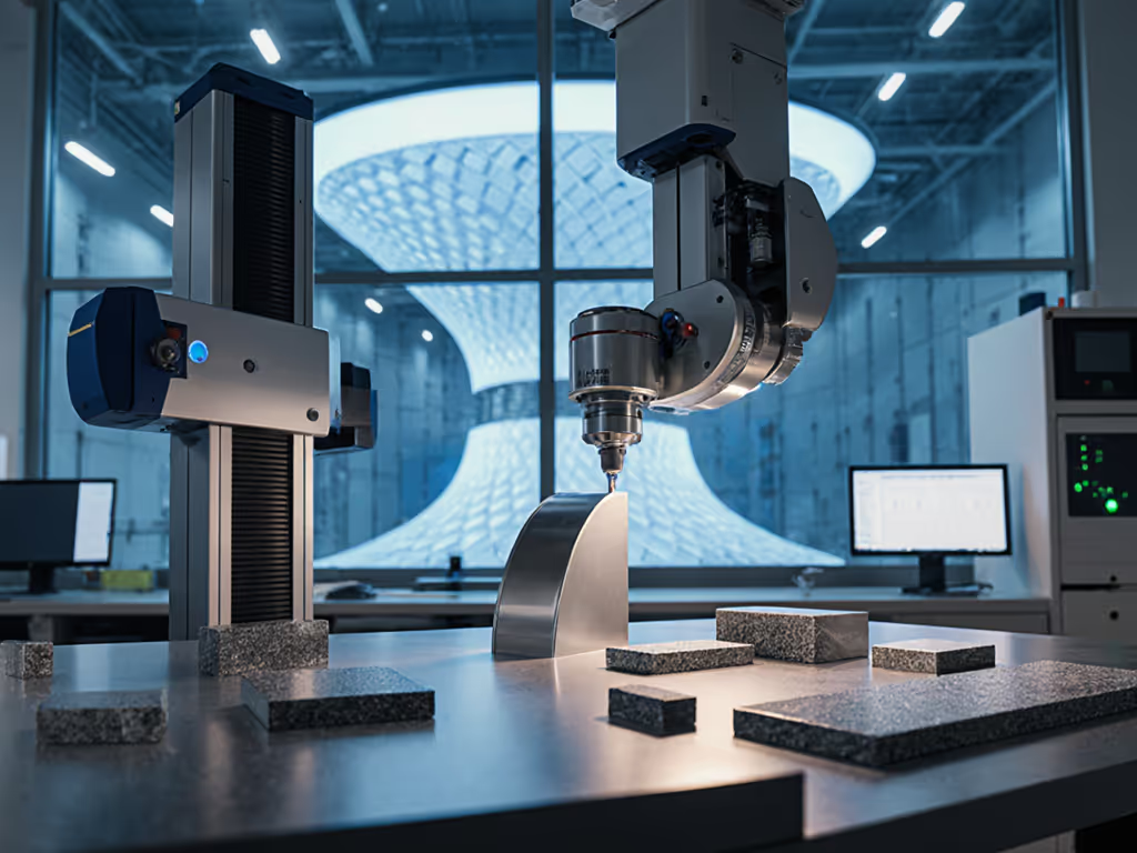
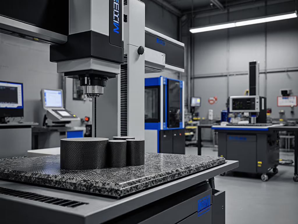
5. CMM-Based Measurement with Carbon Fiber Extensions
What it does: Coordinate measuring machines fitted with carbon fiber probes or extensions maintain measurement accuracy while reducing thermal drift. ZEISS REACH CFX is a portfolio of carbon fiber extensions that are customized for different CMMs to maintain high accuracy levels.
Practical specs: Carbon fiber's low CTE means the probe remains stable over typical shop temperature swings (±5°C), unlike aluminum or steel extensions that expand and skew your offsets.
Best for:
- Dimensional inspection (holes, pockets, edge profiles) on composite parts
- Shops that already own a CMM and want to extend its capability to composites
- Parts where both geometry and surface form matter
Operator reality: Technique is critical. Carbon fiber is brittle; too much probe force will chip the part. Use a light touch and soft-probe settings. Document your force settings in the work instruction, exactly how hard the probe pushes. If operators thumb the probe pressure differently (and they will, under shift pressure), your GR&R will balloon. A simple teach-back: Show me where you're holding the probe before they run a batch.
Hidden cost: Custom carbon fiber extensions ($10k-$40k per CMM), probe maintenance, and periodic re-qualification.
Step-by-Step: How to Pick Your Tool
Step 1: Define Your Tolerance Stack
Start with the part drawing and your process risk assessment. For a structured framework, see our tool selection by tolerance guide. Ask:
- What defect will kill this part in service? (Delamination? Fiber misalignment? Void size?)
- What tolerance must I hold? (±0.5 mm? ±2°?)
- What's my measurement requirement ratio? (10:1 accuracy? 4:1?)
Example: A landing gear bracket must have fibers aligned within ±3° and zero delamination larger than 5 mm². Your tolerance is ±3° and 5 mm² max void. Your test accuracy ratio is 4:1, so your measurement uncertainty must be ≤ 0.75° and ≤ 1.25 mm².
Step 2: Match Defect Type to Method
| Defect Type | Best Method | Speed | Cost/Part |
|---|---|---|---|
| Fiber misalignment (surface) | Fiber orientation scanning | Very fast (< 5 min) | $50-$200 |
| Internal delamination | X-Ray CT | Moderate (20 min) | $800-$2,500 |
| Subsurface voids (thin skins) | Thermography | Fast (10 min) | $100-$500 |
| Dimensional out-of-spec | CMM + CF extensions | Moderate (15 min) | $50-$150 |
| Incoming material quality | Digital microscopy | Fast (5 min) | $10-$50 |
Step 3: Calculate Measurement Uncertainty
Don't guess. For each method, document:
- Instrument uncertainty (from the tool's spec sheet or calibration cert)
- Environmental uncertainty (temperature swing, vibration, humidity)
- Operator uncertainty (repeatability from a small sample of repeat measurements)
Add them in quadrature: U_total = √(U_instrument² + U_env² + U_operator²). If your total uncertainty exceeds 25% of your tolerance, you're at risk. For audit-ready documentation paths, review our ISO/IEC 17025 accreditation guide. Step up to a better tool or tighten environmental control.
Step 4: Pilot on Real Parts
Run a small batch (10-15 parts) through your chosen method. Measure each part three times, with different operators if possible. Calculate GR&R:
GR&R % = (5.15 × σ_repeatability) / Tolerance × 100
If GR&R < 10%, you're in the clear. 10-30% is acceptable with process discipline. > 30%, back to the drawing board.
Building Repeatability into Your Workflow
Here's where most shops stumble. They buy a great tool, run one audit cycle, then watch measurement drift creep in over weeks. Why? Because the human part of the system wasn't engineered.
A simple example from my own experience: We swapped a beloved digital caliper after discovering operators were applying different thumb pressure when taking measurements. One team member would gently rest the part; another would clamp it. The difference? 0.15 mm of hysteresis. A force-limiting device and a two-minute teach-back cut our GR&R from 38% to 12%. The part didn't change. The handling did.
Operator Technique Checklist
Create this for every metrology station:
- Pre-measurement clean: Dry the part and tool. Remove coolant, chips, dust. (5 minutes)
- Stabilization: Let the part sit on the fixture for 2 minutes before measuring. Temperature equilibrates.
- Probe force or caliper grip: Define exactly how hard. Show a photo or video. Gentle contact, like shaking hands, not crushing a can. (Teach-back: operator demonstrates.)
- Measurement point: Mark reference points with layout fluid or a drawing annotation so operator measures the same location every time.
- Record data: Paper or digital. Immediate entry, don't trust memory.
- Environmental check: Log temperature, humidity (if your method is sensitive). Builds a record to explain drift.
Visual Anchors
Don't write a 20-page procedure. Laminate:
- A photo of correct probe placement
- Example good and bad part images
- Go/no-go gage examples
- Calibration due dates (red flag if overdue)
Post these at the workstation. Operators glance in 5 seconds. That's repeatability.
Safety and Compliance Reminders
- X-Ray systems require interlock checks and badges; never disable safety features.
- Thermography cameras can overheat if used continuously; follow cooldown intervals.
- CMM probes are fragile; never force a part into position.
- Store carbon fiber coupons in a stable, dust-free environment to prevent moisture absorption (it shifts CTE).
The Integration Question: SPC and QMS
Measurement data is only as useful as your ability to act on it. If your tool can't talk to your SPC software or your QMS demands paper certs that never get filed, repeatability falls apart under audit pressure. To avoid manual data entry and speed up SPC, consider these wireless measurement tools with seamless SPC integration.
Before you buy, ask:
- Does the tool export data in a format your SPC system accepts (CSV, XML, Bluetooth integration)?
- Does the vendor provide a calibration certificate with uncertainty estimates that satisfy ISO 9001 or AS9100?
- Can you set up alarm limits (Cpk, out-of-control signals) that trigger real alerts?
If the answer to any of these is we'll figure it out later, don't buy yet. Later never comes on the shop floor. You need the system to work for your operators, not against them.
Summary and Final Verdict
Carbon fiber metrology is a spectrum, not a single tool. Fiber orientation scanning is your speed play for high-volume production. X-Ray CT is your surgical precision for critical parts and failure investigation. Thermography fills the gap for large panels. Digital microscopy keeps your incoming material honest. And CMMs with carbon fiber extensions handle dimensional geometry without the thermal headaches.
The catch: No tool guarantees repeatability without operator discipline. You can own the world's best fiber-orientation scanner, but if your crew doesn't follow a checklist or understand why probe force matters, your GR&R will hit 40% and stay there. Measurement systems are workflows, not appliances.
Here's my checklist for your next tool purchase:
- Match your tolerance to the tool's uncertainty budget. (4:1 ratio minimum.)
- Pilot on real parts for a full production cycle. (Not a sales demo.)
- Calculate GR&R before you commit. (< 10% is the goal.)
- Build a one-page technique card for your crew. (No jargon.)
- Verify data integration with your SPC/QMS. (No islands.)
- Document environmental controls and calibration intervals. (For audits.)
- Train your best operator first, then have them teach others. (Peer credibility matters.)
Then, train it, then trust it. Once the system is locked in (technique, environment, tool calibration), measurement becomes a reliable lever for quality. You'll hit your Cpk targets, pass audits cleanly, and sleep better knowing your parts are truly conforming.
The investment isn't in the tool. It's in the habit. Build the habit first; the tool just captures it.
Related Articles