Coating Thickness: Magnetic Induction vs Eddy Current Selection Guide
By Marcus O’Neal • 4th Dec
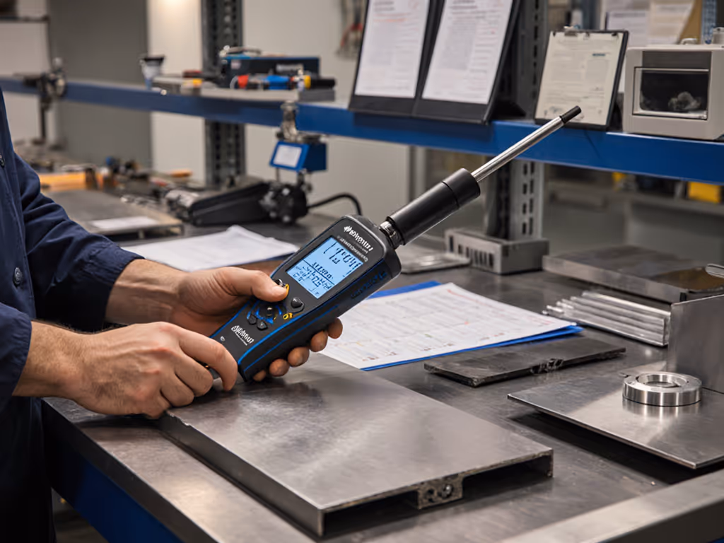
When selecting instruments for coating thickness measurement, understanding the fundamental difference between magnetic induction vs eddy current methods isn't just technical nuance, it is your first line of defense against audit findings and production scrap. If scrap and rework are costing you, review the common measurement error types that quietly inflate costs. As a former calibration lab tech turned quality advisor, I've seen too many shops scramble when auditors question their surface finish verification process. The right choice hinges on substrate conductivity, coating properties, and (critically) your traceability readiness. Let me walk you through exactly how to match these methods to your specific quality control protocols.
Frequently Asked Questions: Your Field Guide to Method Selection
How do magnetic induction and eddy current principles actually differ?
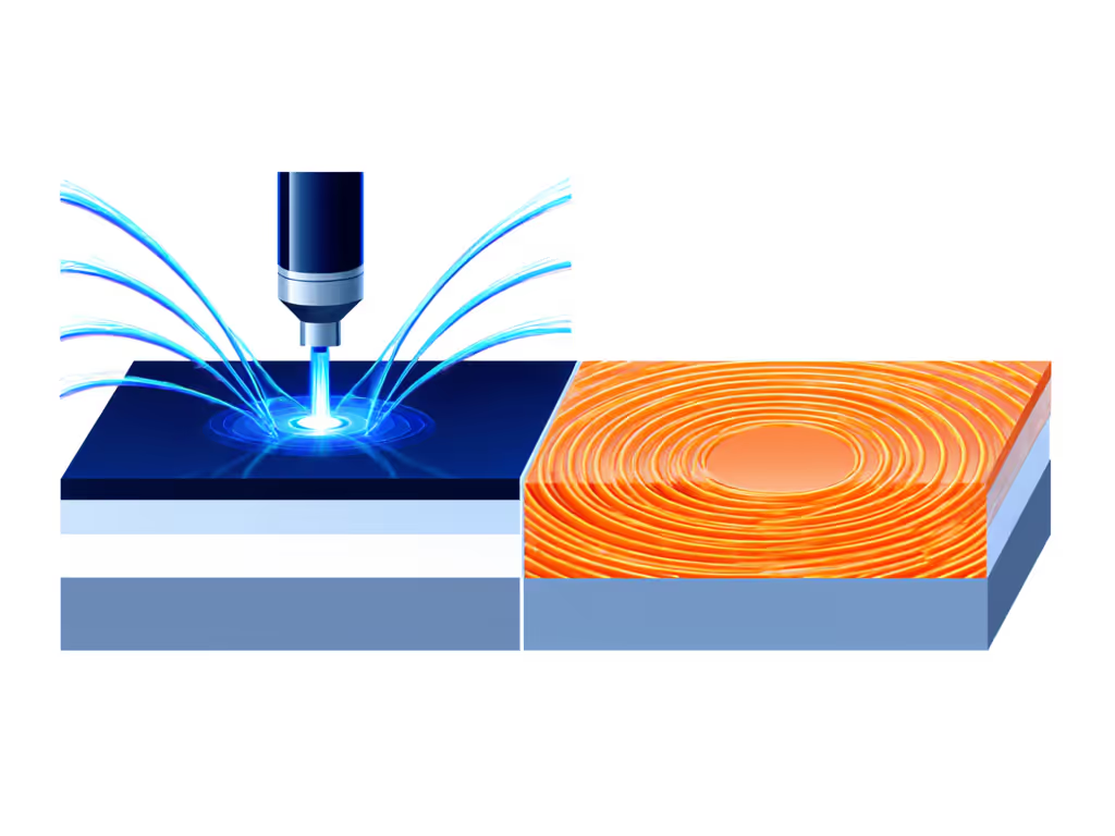
At their core, both methods are non-destructive and work by detecting electromagnetic interactions between the probe and substrate, but their physics dictate completely different applications. I keep this comparison chart taped inside my metrology cabinet for quick reference:
| Parameter | Magnetic Induction | Eddy Current |
|---|---|---|
| Substrate Type | Ferrous metals (steel, iron) | Non-ferrous metals (aluminum, copper, brass) |
| Coating Requirement | Non-magnetic coatings only | Electrically non-conductive coatings only |
| Key Physics | Measures magnetic flux density through coating | Measures impedance changes from induced eddy currents |
| Critical Limitation | Fails completely on non-ferrous substrates | Fails on magnetic or conductive substrates |
| Typical Uncertainty | ±(1-3% + 0.1 µm) | ±(1-5% + 0.2 µm) |
"The magnetic induction method works because thicker non-magnetic coatings increase magnetic reluctance between the probe's magnet and ferrous substrate," I explain during my shop floor trainings. "Eddy current relies on high-frequency fields inducing circular currents in conductive substrates, and the coating thickness changes how much those currents oppose the probe's field."
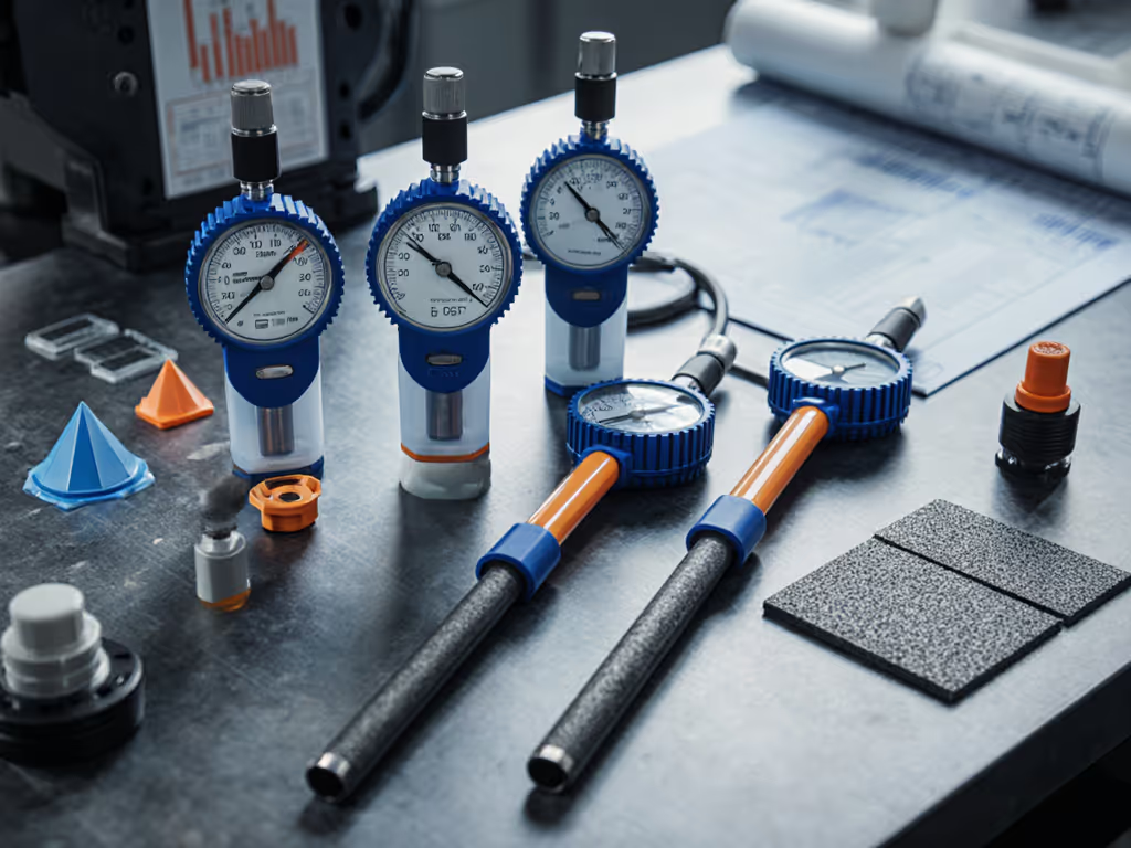
Many technicians confuse these because combination gauges ("dual-mode" instruments) exist, but the underlying physics remain distinct. I once audited a job shop where they tried measuring anodizing on aluminum with a magnetic probe because the gauge had a "dual-mode" label, resulting in 100% scrap in a medical device batch. The sales rep hadn't clarified that "dual-mode" means two separate sensors in one housing, not one probe that magically works everywhere.
How do I determine which method to use for my specific materials?
Follow this decision tree I've refined through 12 years of aerospace audits. Grab your substrate sample and ask:
- Is the substrate attracted to a magnet?
- Yes → Magnetic induction is your only option for non-magnetic coatings (paint, powder coat, enamel)
- No → Proceed to question 2
- Is the substrate electrically conductive? (e.g., aluminum, copper, brass)
- Yes → Eddy current works for non-conductive coatings (anodizing, paint, plastic)
- No → Neither method applies (use ultrasonic instead)
Critical exceptions auditors always check:
- Stainless steel: Austenitic grades (304, 316) are non-magnetic — eddy current required even though it's "steel"
- Zinc plating: Magnetic induction works only if measuring non-magnetic topcoat over zinc (not zinc thickness itself)
- Conductive coatings: Eddy current fails on chrome-plated aluminum since chrome conducts
I recall a supplier who nearly lost their Boeing contract because they measured zinc-nickel plating on steel with eddy current (thinking "nickel = non-ferrous"). The nickel content made it slightly conductive, but the ferrous base required magnetic induction. Always verify substrate properties with your material certs, never assume.
What environmental factors impact accuracy, and how do I document them for audits?
This is where most shops fail their ISO 9001 audits. Temperature alone can induce 0.5-2% drift per °C in both methods, yet I've seen calibration records with blank "environment" fields. Here's my shop-ready checklist for audit-proof industrial coating measurement: If roughness is a recurring issue, see our surface roughness measurement guide.
Environmental Control Checklist
- Temperature: Document room temp and substrate temp (±2 °C stability required)
- Curvature: For radii <50 mm, apply curvature correction per ISO 2178/2360
- Surface roughness: Ra > 2.5 µm requires special calibration (per ASTM D7091)
- Probe pressure: Consistent 2-5 N force (varies by probe type, record your standard)
- Edge effects: Measurements within 25 mm of edges invalidated
During an AS9100 audit last year, the auditor specifically asked for our temperature logs during CMM room coating checks. When we showed the full traceability chain (from NIST-calibrated thermometer to environmental logs), I saw his pen stop hovering over the NC report. Audit anxiety evaporates when you show your chain of traceability for every variable. That experience cemented my belief: traceability isn't paperwork, it's production armor.
How do I build a defensible uncertainty budget for my measurements?
Most spec sheets list "accuracy" without context, but auditors want your actual uncertainty budget. Start with repeatability studies on your specific parts:
- Calibration uncertainty: From your certificate (typically 1.5–3% of reading)
- Resolution error: Half the smallest digit (e.g., 0.1 µm → ±0.05 µm)
- Environmental contribution: Documented temp drift (e.g., 0.8%/°C × ΔT)
- Probe wear: Measure standard 10 times daily; track slope
- Operator variation: GR&R study across 3 techs
"Trace it, budget it, then trust it under audit" isn't just my mantra, it's how you sleep soundly during certification cycles.
For critical aerospace work, I require a 4:1 test accuracy ratio (TAR). If your coating tolerance is ±5 µm, your uncertainty budget must stay below ±1.25 µm. Most handheld gauges hit ±(1% + 0.5 µm), so they're fine for 50 µm coatings but useless for 10 µm anodizing specs. Always match instrument capability to your tolerance, not the marketing brochure.
What are the most common application mistakes, and how do I prevent them?
Through hundreds of metrology assessments, these errors cause 80% of coating thickness failures:
Audit-Failure Hotspots
| Mistake | Risk | Prevention |
|---|---|---|
| Using magnetic probe on stainless steel | False thin readings (coating rejected) | Verify magnetism before measuring |
| Ignoring substrate thickness | Skewed readings if <1 mm | Use foils for thin substrates per ISO 2360 |
| No curvature correction | 15–40% error on tubes | Calibrate on actual part geometry |
| Dirty calibration standards | Gradual drift | Clean standards with isopropyl alcohol |
| Measuring near welds | Ferrite variations | Mark "no-measure" zones on fixtures |
One medical device manufacturer failed their FDA audit because their eddy current gauge was calibrated on flat aluminum but used on curved catheter hubs. The concave surfaces created readings 22% thinner than actual, putting critical corrosion protection out of spec. Always calibrate on representative geometry. I now specify in our procedures: "Calibration must replicate production part geometry within ±5° curvature."
How do I integrate these gauges into production without slowing workflow?
Industrial coating measurement shouldn't mean production standstills. Here's how I've optimized workflows across 37 job shops:
-
For high-volume lines: Mount fixed eddy current sensors at conveyor exits (e.g., automotive trim lines). Set pass/fail relays to auto-divert out-of-tol parts. Document environmental compensation algorithms.
-
For critical aerospace: Use gauges with Bluetooth that push data directly to your QMS. But (crucially) validate data integrity first! For proven options that stream data to SPC and IoT systems, explore our wireless measurement tools. I've seen Bluetooth errors corrupt 12% of readings when sensors neared 480 V bus bars.
-
For field maintenance: Dual-mode gauges (magnetic + eddy) prevent tool confusion. But require techs to log the active mode in reports — "dual mode" isn't traceable by itself.
My golden rule: Never use a gauge that can't output its calibration certificate ID with each reading. During a recent Nadcap audit, this simple step eliminated hours of cross-referencing. When the auditor saw traceability embedded in every measurement record, he nodded and moved on. That's the power of audit-ready documentation.
Final Takeaway: Precision Through Discipline
Selecting between magnetic induction and eddy current isn't about which gauge is "better," it's about engineering a measurement system that stands up to your specific production realities and audit requirements. Document your environmental controls, validate your uncertainty budget against actual parts, and always, always, show your chain of traceability. The moment you treat measurement as a capability rather than a tool, you'll see fewer scrap tickets and smoother audits.
For your next step: Download my free [Coating Thickness Uncertainty Calculator], it auto-generates audit-ready uncertainty budgets using your calibration certs and production data. Because when the auditor asks for your traceability chain, wouldn't you rather have it ready in 30 seconds?
Related Articles